Category Archives: Dynamics

Vibration isolation of a plate

The topic of this blog post is one I started thinking of when a friend of mine presented the idea of whether the flexibility of a relatively thin concrete plate affects the response of a vibration-isolated foundation. In other words: should the behaviour of the plate in itself be taken into account in a situation like the one described here (without taking into account any possible other objects attached to the plate itself)?

Well, let’s do some testing.

The setup

The dimensions of the plate

The dimensions of the plate (whoops, t should be 8 cm)

These are the dimensions of the plate. The vibration isolators are chosen to be 10cm x 10cm & have a uniform dynamic stiffness of $$E = 3 \mathrm{MPa}$$ and a thickness of $$t = 2.5 \mathrm{cm}$$. The values I chose from concrete are $$\rho = 2.5 \mathrm{kg}/\mathrm{m}^3$$ and $$E = 27 \mathrm{GPa}$$.

A cool gif

Steady state response / sine sweep

Steady state response / sine sweep

What you’re seeing above is basically the result of a sine sweep on a damped system, where a sinusoidal force is placed at 20% from the outer right corner of the plate. So, we have a point force with a constant amplitude and a specific frequency attempting to vibrate the plate.

Note that the deformations are waaaayy exaggarated throughout this post.

One can clearly see that the deformation gets smaller as the frequency increases. Thus, a smaller portion of the exciting force is transfered to the foundations. Also note that in the beginning, mostly one corner vibrates but as we approach the modes at ~36 Hz (the modes will be shown later in this post) the plate starts to pivot/swing around the middle axis. So we’re moving from a mix of modes 1 and 2/3 towards modes 2/3.

Some theory

Starting from $$\mathbf{M}\ddot{x} + \mathbf{C}\dot x + \mathbf{K} x = \mathbf{f}$$, I solved the dynamic system $$(-\omega^2\mathbf{M}+{i\mkern1mu}\mathbf{C}+\mathbf{K})\mathbf{x}=\mathbf{f}$$ describing the steady state solution with a sinusoidal excitation. I used python, and obtained the mass/stiffness matrices using finite element analysis. The eigenfrequencies are calculated using regular analysis (from $$\textbf{M}^{-1}\textbf{K}$$).

The Mindlin–Reissner plate theory with bilinear elements was used for the plate. Also, I used regular spring elements lumped at the nodes for the vibration isolation (vertical shear deformations of the isolators are not central at the lowest frequencies). For the damping matrix, I used rayleigh damping with nothing but the stiffness matrix-related term with a value of 0.0075. I applied the damping directly to the global system.

Only vertical movement is taken into account here.

The eigenmodes & resonant frequencies

Alright! What are the lowest frequencies the system will resonate on? Or, to put it another way, what are the lowest eigenmodes, and the corresponding eigenfrequencies? The lowest mode corresponds to the one obtained from the formula for a mass-spring system, $$f_0 = \frac{1}{2 \pi}\sqrt{\frac{k}{m}}$$, which in this case gives $$f_0 = 22.85 \mathrm{Hz}$$.

Mode 1 @ 22 Hz

Mode 1 @ 22 Hz

Mode 2 @ 36 Hz

Mode 2 @ 36 Hz

Mode 3 @ 37 Hz

Mode 3 @ 37 Hz

Mode 4 @ 188 Hz

Mode 4 @ 188 Hz

Mode 5 @ 201 Hz

Mode 5 @ 201 Hz

The response of the system

How well does this system perform? What are the effects of these modes?

First, let’s try placing the force in the absolute middle. This would be the ideal case, when we can be sure that everything works as well as it can. Let’s also, to begin with, consider an undamped system. Note that concrete in itself definitely has some structural damping, so the response is by no means correct here:

Centered force, no damping

Centered force, no damping

Alright! We can see a sharp peak at around mode 4. Mode 5 isn’t visible, as the force in the absolute middle has no way of waking it up. Note that we’re examining an undamped system here, so this is something which would happen if the concrete in itself wouldn’t dissipate energy at vibrations around ~200 Hz (which it in reality does).

Ok then! What happens if we add some damping to the system? Let’s also apply the same kind of damping to the isolating pads.

Center force, with damping

Center force, with damping

Suddenly we can see that the mode at around 188 Hz vanishes completely. This is because the type of damping we added affects higher frequencies quite a bit. I chose a coefficient which very roughly should correspond to the damping behaviour of concrete, but I did not do any thorough research here so please note that the resonance could in reality very well be somewhere between the two previous figures. Still, the results seem to very strongly indicate that the mode at around 188 Hz shouldn’t be visible in a situation like the one described here.

Ok then! Let’s try moving the force a bit. Let’s move it so it’s 20% from both sides. First, let’s examine the case without damping. What does the response look like now?

Noncentric force, no damping

Noncentric force, no damping

Apparently the force is situated in such a place that mode 4 isn’t really excited. Instead, we can see that mode 5 is clearly visible.

Once again, let’s see what happens when we add some damping.

Noncentric force, with damping

Noncentric force, with damping

We can see that only the three first modes seem to affect the result. Still, I’d say that it’s really important to notice that the first three modes actually affect the result quite a bit. This is also clearly visible in the animated gif at the beginning of the post.

Conclusion

The modes of the plate in itself are very central when the structure in itself doesn’t have strong damping characteristics. This would be the case if the plate was made of steel, for example. If the plate is made of homogenous concrete (no rebar is taken into account here), the results strongly indicate that only the modes where the structure can be assumed to act as a rigid body seem to affect the result.

Thus, in a case like the one above, it should be enough to consider the plate as a perfectly rigid structure. Still, the results strongly indicate that if the excitation isn’t perfectly centered, other modes than the lowest one can have a strong effect on the performance of the isolating system. Also, if there is reason to suspect that the modes of the plate in itself aren’t damped, it might be useful to examine them as part of the system.

Listening to vibrations

Update: here’s a small tune I made to demonstrate what the resulting sample would sound like as an instrument:

I’ve always been fascinated by how things, especially sound waves, look like in slow motion. By examining something in slow motion, somehow even complex phenomena start to seem intelligible.

In this post, I’m examining the behavior of a very simple instrument in slow motion. The physics are very much the same as when examining vibrations in structures, but instruments are (very much) nicer to listen to. The principles shown here are naturally applicable to larger scale phenomena that occur in structures of different kind (buildings, bridges, etc).

The instrument

The instrument will consist of a cantilever beam made out of steel, with a length of 20 cm. The cross-sectional dimensions of the beam are 2 cm x 2 cm. The instrument will thus resemble something like a simple vibraphone / glockenspiel / large music box.

We’ll use the same principle to get the sound of the beam as an electric guitar uses to pick up the sound of a string, by placing a (virtual) pickup at a position 3/4:th to the left of the tip of the beam (or 1/4:th from the left of the beam, whichever suits your fancy).

What will happen if we hit the very tip of the beam, with a very sharp, impulse-like force (even sharper and quicker than what’s possible with the hammer in the picture)?

The result

First, it should be noted that the same principle is used as when an electric guitar picks up the sound of a string. The pickup transforms the deflection at a certain point on the string (or in this case, beam) directly to sound. The resulting sound for the beam is as following:

To see what the beam looks like directly after being hit by the sharp impulse, examine the resulting deformation of the beam as a function of time here (click on the blue area to load the content). The sound is generated from the movement of the circle in the direction of the y-axis.

http://kaistale.com/blog/130722beam1d/animation.html

Some things to notice when watching  the time lapse of the deformation:

  • There’s a transient part at the very beginning (slightly visible in the 0.0015 s time span) which attenuates very quickly. This is the part of the response where standing waves (resonances) have not yet formed.
  • The two lowest natural frequencies (resonances) can be seen clearly; one at 464 Hz and another at 2910 Hz. The third natural frequency, 8150 Hz, can be seen at the very beginning of the response.
  • For this setup, the higher frequencies attenuate quickly. In the end, only the lowest natural frequency, 464 Hz, can be heard. This gives the distinct pitch you can hear in the sound sample above.

The theory

I’m using finite element analysis to examine the behavior of the beam. The theory is the same as in the previous post, but I’ve also calculated the mass matrix for the beam. I’ve used 25 elements for the beam, thus solving a 50-degree of freedom system. Note that I’m using the Euler-Bernoulli beam theory, so some simplifications are made.

The damping was done using Rayleigh damping. For those familiar with this type of damping, the value for $$\alpha$$ was 1e-05 and the value for $$\beta$$ was 1.5e-06. I chose these values simply on the basis of listening to which damping values sounded better than others, not much thought were put into them. They seem surprisingly small as compared to other values I encountered online, maybe someone more acquainted with Rayleigh damping could offer me their opinion on this?

I used the Newmark algorithm for time-stepping, with a value of 0.5 for both $$\beta_1$$ and $$\beta_2$$.

The methods

I used Python for the calculations. Python is ideal for such an endeavor, and free! SymPy provided me with the tools I needed to solve the necessary equations, while NumPy did the calculations for me.

I saved the resulting calculations as a binary file, which only contained the necessary information. For example: only one byte / element describes the deformation at each time step in the animation seen above, as 8 bits is more than enough in this case.

I wrote a script that loads up these binary files (of which 3 can be seen above). The deformations can be examined as a function of time. I’m quite happy about how it turned out, even though some parts of the code are quite hacky-ish. You can see the code for the javascript here. Note that this code only displays the data from the binary files, the binary files have been calculated using Python.

Thoughts for the future

Perhaps the parameters could be tweaked a little, so the sound would be closer to the sound from a music box (which is the instrument I think the model most closely resembles). Also, the Timoshenko beam model would be nice to try, for comparison. All in all, this post was a nice exercise in programming Python, JavaScript and doing finite element analysis in the time domain.

Mass-spring systems should be understood before they are used

Mass-spring systems are often used to model the behavior of an isolated vibrating system.

The mass-spring viewpoint should not be utilized in cases where the system can not be reliably modeled as a mass-spring system. The importance of the static compression of the isolating material, due to gravity, is also overemphasized and often misunderstood.

Some important points:

  • The mass isolates vibrations by resisting change of momentum. Usually: the more mass, the better. The weight (due to gravity) has very little to do with the isolation, it’s the mass that matters!
  • The spring’s main purpose is to carry static forces (for example the weight). It will also try to resist the displacements of the mass, which means that it will transfer forces to the foundations. From the perspective of isolating vibrations, the spring should be as loose as possible, to allow for the mass to vibrate freely.
  • The mass-spring combination only works on frequencies higher than the resonance frequency.
  • Ideally, there would be no “spring”, but it’s impossible in practice.

Simplifying rotating parts

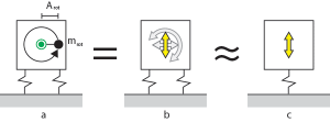
Let’s start from the very basic reasoning behind why the mass-spring perspective is so common when designing vibration isolation. Consider case a. We have a machine, with a part rotating around some axis.

Case b shows the varying forces such a movement creates. Perpendicular forces exist relative to the x-axis and y-axis. The varying force in the direction of the x-axis, together with the resisting force at the support, also create a moment of force (kind of like attempting to tip the machine over). The vertical component of the force often creates a moment of force, as well. As does accelerating or decelerating angular motion.

In practical cases, it has been shown that it’s often enough to consider the sinusoidal force shown in case c (but it’s not always enough!).

Note that this model assumes both the machine and the support to be perfectly rigid. Note also that the force required to keep the rotating mass in bay will rise along with the frequency ($$\omega^2$$)! I think I will return to this in another post.

The equilibrium of the system

So far we have simplified the system to a sinusoidally varying vertical force, acting on a mass on a spring.

We will describe the system using these parameters:

  • The mass of the machine
  • A varying force directed on the machine
  • The varying displacement of the machine
  • The spring constant, which we’ll assume to be constant (linearly elastic)

We now have five different sources for forces:

  1. $$F_{m} = ma = m\ddot y$$, caused by the mass/momentum of the machine which resists acceleration
  2. $$F_{k} = k y$$, caused by the compression of the spring
  3. $$F_{c} = cv = c\dot y$$, caused by various energy losses which are directly proportional to the speed of the displacement
  4. $$F_{e}$$, external forces which we feed into the system.
  5. $$F_{g}$$, the force of gravity pulling down the mass

Using the principle of equilibrium (Newton), the sum of these forces must be 0.

$$F_k + F_c + F_m + F_e + F_g = 0$$

$$F_g$$ can be discarded in our calculations. I’ll soon explain why.

Calculating the natural frequency of the system

We know that such a system oscillates naturally at a specific frequency. To calculate this frequency, we assume three things:

  1. The motion is sinusoidal
  2. There are no external forces ($$F_e$$)
  3. The damping factor ($$F_c$$) approaches zero, allowing for the system to oscillate freely

By assuming the motion follows the function $$y(t) = A\sin(\omega t)$$, we get the following equation:

$$F_k + F_m + F_g = k(y(t) + y_0) + m\ddot y(t) + mg = k A\sin(\omega t) – m A \omega^2\sin(\omega t) = 0$$,

where $$y_0$$ is the compression caused by the pull of gravity.

$$k y_0$$ has to be equal to $$m g$$ for the system to balance out (Hooke’s law), which means that we can throw the effect of gravity out of the equation. Intuitively this can be explained as following: as the effects of gravity and the static compression of the string ($$k y_0$$) constantly cancel each other out, only the vibrating part of the displacement ($$y(t)$$) makes any difference. The force caused by the vibrating part of the displacement is still directly proportional to the spring constant. Gravity (and as such the static compression of the spring) makes no difference. Gravity only affects the situation if the spring constant changes because of it, not because it compresses the spring or adds a constant downward force to the mass. This holds true for all constant forces, so constant forces should never be included in a vibrating mass-spring system to avoid confusion! They should only be used to calculate the correct spring stiffness, which is almost always very nearly linear when the vibrations are small.

The forces will balance out when $$\omega = \sqrt{\frac{k}{m}}$$, or $$f_0 = \frac{1}{2 \pi}\sqrt{\frac{k}{m}}$$.

Note that this is the combined natural frequency of the spring and the mass! This might seem obvious now, but when we replace the mass and spring constant with something else, it might not be that obvious. The compression of the spring, using Hooke’s law, will be $$mg = k\delta x$$. Inserting this into the formula will give $$f_0 = \frac{1}{2 \pi}\sqrt{\frac{g}{\delta x}}$$. This formula is often used for practical purposes, but effectively hides the real parameters the natural frequency is based on!

Calculating the forced response of an undamped system

We will consider the steady state response, meaning the response of the system after being excited at a specific frequency for a long time (when everything balances out). We will assume the mass will move at the same frequency as the force exciting it.

The equilibrium formula shown earlier will now look like this:

$$m \ddot y(t) + k y(t) = F(t)$$

Assuming the machine will be excited according to the function $$F(t) = F\sin(\omega t)$$ (ignoring everything else for now) and the machine moving according to the function $$y(t) = A\sin(\omega t)$$ we get the following formula:

$$-m A \omega^2 sin(\omega t) + k A sin(\omega t) = F_0\sin(\omega t)$$

Solving for A (the amplitude of the motion caused by the force), we get the following formula:

$$A = \frac{F_0}{-m \omega^2 + k}$$

Note that this describes the displacement of the mass. I think the following concept is really important to understand; the force transmitted into the foundations is directly proportional to the displacement. As the spring constant approaches zero (let’s imagine the mass floats in space, for example), the system will still vibrate with an amplitude of $$\frac{F_0}{m \omega^2}$$. Increasing the mass will decrease the amplitude of the vibration, also when there is no spring.

To get the force transmitted into the foundations of the machine, we need to multiply the displacement with the spring constant $$k$$ (according to Hooke’s law). From this, we get the relation of the transmitted force to the original force $$\frac{F_{tr}}{F_0}$$:

$$\frac{F_{tr}}{F_0} = \bigg\vert\frac{1}{\frac{-m}{k}\omega^2 + 1}\bigg\vert$$

The formula nicely shows us a few things:

  • The resonant frequency is at $$\omega = \sqrt{\frac{k}{m}}$$, which is the same as earlier
  • The effect of decreasing the stiffness of the spring
  • The effect of increasing the mass of the machine

Thoughts

Please note that this has been a significant simplification of the situation. Ideally, the simplification only works for cases where the vibrating force is purely vertical, and acts in the exact direction of the centre of mass of the object.